Density Compensated FAD (Free Air Delivery) Meter with AVFD technology

Compressed air systems are found in most of the industries and are typically used for production, processes for material handling, Instrument air and for refrigeration. Compressed air systems are typically the least energy efficient among all motor systems.
Industrial compressed air systems are notoriously inefficient. Compressed Air systems are often taken for granted. Most people think it is free because air is free. However, compressed air is one of the costliest utilities.
According to a survey, 10% of total industrial electricity is consumed by Air compressors. Over the 10 year life of an air compressor, more than 70% of the operating cost goes to electricity. With decades of experience designing energy-efficient air compressors, we understand the true cost of compressed air. We also know the potential savings are tremendous. In this article, you’ll learn how to calculate the costs of compressed air — and how to cut them back.
| In most compressed air systems, around 30 % of the compressed air is lost due to leaks, poor maintenance, misapplication and inadequate control. Consequently, efficiency improvements in compressed air systems are particularly important. In fact, in some cases, without knowing, nearly half of all compressed air is wasted. |
| First step towards management is “MEASUREMENT” |
The Cost of Compressed Air
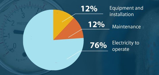
Many people wrongly assume most of the cost of compressed air is in the initial purchase of the machine. In reality, electricity to operate the equipment over time is far more expensive. The equipment itself only accounts for just over 10 percent of the cost of producing compressed air.
| “Air we breathe is free, but compressed air is not” |
Cost of compressed air and monetary saving
Approximate cost of compressed air can be calculated as below.
Cost = (Motor Rating in KW) * (Operating Hours) * (Cost/kWh) / Motor Efficiency
For Example:
ACompressor of 850 SCFM capacity with motor rating of 160 KW @ 125psig, considering motor efficiency of 0.95, 8000 Hrs. of annual operation and Cost/kWh of BDT 7.50tk, cost of compressed air can be calculated as under:
Annual cost of compressed Air = 160 X 8000 * 7.50 / 0.95
= BDT 10,105,2613 tk
Hence, annual electrical bill for a small compressor is around 101 Lakhs taka. If managed well, we can save at least 6-10% of money and that is huge monetary saving of around 6 – 10 Lakhs per year.
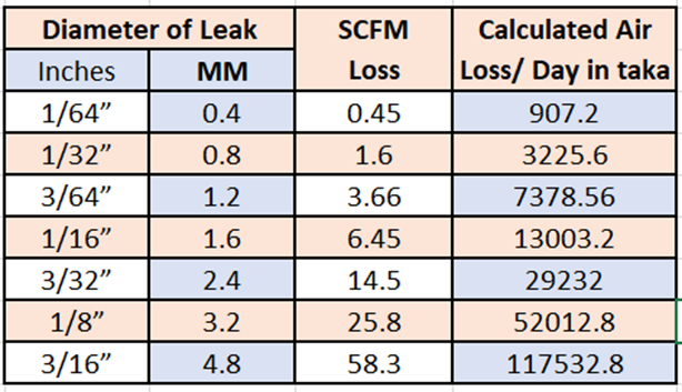
Losses due to leakages:
Air loss is directly proportional to your monetary loss Table mentioned the losses due to leakage from different orifice size (holes).
5 – 8% (Depends on individual compressed air system)
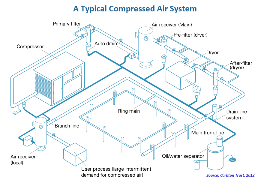
Where does Leakages Commonly occur in Compressed Air System?
Leakage can occur at number of points in a compressed air distribution system. Some of these are listed below:
- Branch Line Connection
- Automatic Drain Trap
- Filter Assembly
- Regulator Assembly
- Rubber Hose
- Quick Coupler
- Isolating Valve
Pressure drop losses: Pressure drop will increase the consumption and unnecessary consumption again means monetary loss.
A rule of thumb for systems in the 7 BarG range is that for every 0.15 BarG increase in discharge pressure, energy consumption will increase by approximately 1 percent at full output flow.
Major sources of Pressure Drop in Compressed Air System are:
- Undersized Distribution Piping
- Line Leakages
- Wrong choice of Flow Measuring Instrument
Approximate Savings: 2 -3% (Depends on the distance between generation and consumption)
Optimized use of compressor bank:
By measuring exact amount of air required for every section or unit in a factory, utility manager can use the compressor bank in a much effective manner.
For Ex. A utility manager is having 4 Compressors of 700 CFM, 2 Compressors of 1500 CFM & 1 Compressor of 2500 CFM. There are 5 different Units A, B, C, D & E where compressed air is distributed. When plant runs on full load, requirement of air is 4500 CFM. But all units might not run at equal load and exact demand for each unit is unknown. So, manager will assign the compressors as per his approximated calculations.
This again results in LOSSES.
SOLUTION: With proper departmental Air Flow Metering, effective use of compressor bank is possible.
Approximate Savings: 1 – 2%
Losses due to unnecessary compressor maintenance:
Maintenance is required if the compressor don’t give desired output but generally compressor maintenance is scheduled on timely basis not on the need basis.
By measuring compressed air at the output, we came to know the exact time of maintenance for compressor.
Approximate Savings: 1 – 2%
Understanding FAD of compressor
FAD stands for Free Air Delivery and is the amount of Atmospheric Air sucked in by the compressor at standard inlet conditions (suction side) of the compressor.
These inlet conditions are as under:
A. Atmospheric pressure of 1 Bar (a).
B. Atmospheric Temperature of 15 / 20 Deg C.
C. Relative Humidity at 0% (100% Dry Air).
D. Motor RPM at 100% of its rated value.
Compressor’s FAD rating tells you only the amount of air it will suck in, and not the air it delivers at outlet under actual conditions.
Calculating FAD
To calculate the free air delivery of a compressor firstly the pressure and temperature at the inlet of the compressor are needed. Then the pressure and temperature of the outlet air along with the volume discharged are also measured. The output volume of the air is referenced back to inlet conditions using the Ideal Gas Law.
P1 * V1 / T1 = P2 * V2 / T2
V1 = P2 * V2 * T1 / T2 * P1
Where,
V1 = Flow Rate at standard conditions or FAD
V2 = Flow Rate at operating condition
P1 = Standard Pressure i.e., 1 Bar A
P2 = Operating Pressure
T1 = Standard Temperature i.e., 15 Deg. C.
T2 = Operating Temperature
For accurate FAD measurement, operating temperature and pressure should be calculated online on real time basis just like instantaneous flow rate.
FAD meter must have integral temperature & pressure sensor for single point measurement.
Measuring Free Air Delivery (FAD)
Typical Applications
- At compressor discharge, mostly after receiver.
- At distribution lines to individual section or equipment.
What is MUST for accurate FAD Meter ?
- It should show reading in both standardised & operational flow unit i.e. SCFM & CFM or Nm3/hr & m3/hr
- It should be compensated to standard temperature & pressure conditions
- It should have In-built temperature & pressure sensor for single point measurement
- It should be pneumatically calibrated i.e. calbrated on Air
- Accuracy should be good.
- Turndown should be as high as possible
Advantages of KROHNE FAD Meter
Density Compensation – Have In-built Temperature & Pressure Sensor for density compensated Flow Masurement of gases.
Pneumatic Calibration – All our Flow Meters are calibrated on Pneumatic Rig (Air) upto the velocity of 70 m/sec. Thus results in better correction factor for better Accuracy.
High Turndown – Our Vortex Flow Meters have turndown of 1:25 (depends on operating parameters). Thus, it increases the lower limit of measuring flow rate and can measure accurate flow during fluctuating load as well.
High Accuracy – Advanced vortex frequency detection (AVFD) technology ensures maximum measurement reliability and stability.
Modular Design – Our Flow Meters are designed in such a way that the electronics can be replaced or changed at site also.
Forged Stainless Steel Design – Housing of our vorex flow meter is machined out of forged steel instead of casting, which result in better performance of product.
Weld neck flanges – Our vortex flow meter flanges are weld neck type.
Highly Suceptible to Noise & Pipe Vibrations – With the help of AVFD technology & two piezo electric sensors our flowmeter can make out the difference between actual flow and unwanted vibrations.
HART Output – By default 4 – 20 mA + HART + Pulse output signal.
No moving part – No wear and tear, long life, frequent recalibration not required.
Ruggedness – Fully-welded stainless steel construction machined out of steel blocks and much superior to casted steel. Also, providing high resistance to corrosion.
For any further details, please contact with our Krohne Marshall representative in Bangladesh.
Zahid Hossain | Product Manager – Integrated Solution
INTOPS-Bangladesh Operations
Forbes Marshall Pvt. Ltd.
Ahmed Tower, 7th Floor, South East Corner,
28 & 30, Kamal Ataturk Avenue, Banani, Dhaka-1213 | Bangladesh |
Mob: +8801701229577 (Corporate); +8801728611021 (Personal);
Email: zhossain@forbesmarshall.com
Website: www.forbesmarshall.com